
DISTRIBUTED TEMPERATURE SENSING
SUPPLIED WITH RED OPTICAL FIBER

VTI-GL-100C

Self-powered wireless temperature sensors and the GW22-D gateway. Thermal alarms go straight into your existing SCADA over IEC 60870-5-104 — no middleware server.

BLE 2.4 GHz · Order code TBR22

10-year design life · Standby bays

LoRa AS923 · Up to 3 km LOS
Bolted joints, cable lugs, disconnector and breaker contacts, bushing terminals. Oxidation, loss of clamping force and moisture corrosion raise contact resistance gradually. The heat produced rises with the square of the current, so the process accelerates itself.
Two or three surveys a year are two or three moments out of 8,760 hours. A defect can start and develop between them.
Temperature rise scales roughly with the square of the load factor. A 1 K difference measured at 30 % load corresponds to about 11 K at rated load.
Enclosed switchgear, RMUs and insulated joints are invisible to a camera. Measuring means opening energised panels.
One VTI sensor at a 30-minute reporting interval records 17,520 readings a year, with alarms when temperature rises quickly.
High-precision battery-free sensors, dual-band concentrators, distributed fiber optic DTS systems, and AI CBM software designed by VTI Corp for national grid utilities under IEEE 2969 and CIGRE TB 999.
BLE sensor for switchgear, panels and substation bays. Battery (TBR22-B) and temperature-humidity (TBR22-BE) versions.
LoRa sensor for large outdoor switchyards and long distances. Self-powered (VTI-TS-26) and battery (VTI-TS-26-B) versions.
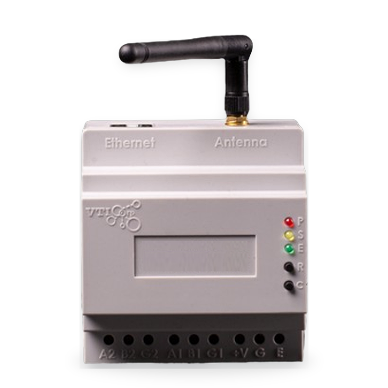
Direct IEC 104 to SCADA, RS-485 for third-party devices, stand-alone operation with 30 days of local storage.

Multi-channel Raman OTDR distributed temperature sensing controller supplied together with VTI red optical sensing fiber for 24/7 continuous linear thermal profiling up to 20 km (±1°C accuracy, 0.5 m spatial resolution, 10.4-inch touchscreen HMI).

Condition-based maintenance platform computing real-time Arrhenius electrical contact degradation kinetics, rate-of-rise thermal alarms, and dispatch integration.
Evaluate parameters to select the optimal sensing modality for your electrical substation or transmission line scope.
| Specification Parameter | VTI-TS-22 (order code TBR22) | VTI-TS-26 Sensor | GW22-D Gateway | Fiber DTS VTI-GL-100C |
|---|---|---|---|---|
| Primary Application | Indoor Switchgear & RMU | Outdoor 500 kV & Lines | Dual-Band Substation Gateway | HV Underground Cables & Tunnels |
| Power Supply | From 1 A depending on model / TBR22-B 10-yr battery | From 1 A depending on model / VTI-TS-26-B battery | 220 V AC/DC | DC 24V, 50W / 110–240 VAC Station |
| Measuring Range | −40°C to +125°C | −40°C to +125°C | Up to 1,000 sensors per gateway | −40°C to +120°C (up to +150°C) |
| Accuracy & Resolution | ±0.2 °C (−10…+65 °C); ±0.5 °C rest | ±0.2 °C (−10…+65 °C); ±0.5 °C rest | Sub-second sync (IEC 104 Master) | ±1.0°C (Res: 0.1°C, 0.5 m / 1 m) |
| Telemetry / Channels | BLE 2.4 GHz (~100 m) | LoRa AS923 (up to 3 km LOS) | BLE 2.4 GHz + LoRa AS923 (Receive-only) | 4 Channels • 20 km (5 km/ch) Raman OTDR |
| Dielectric Testing | Up to 500 kV (HVLAB D04.24/BBTN-01 & D12.23/BBTN-02) | Up to 500 kV (HVLAB D04.24/BBTN-01 & D12.23/BBTN-02) | IEC 61000-4 EMC Level 4 | Optically Isolated Dielectric |
| Enclosure & Display | High-Dielectric V0 Polycarbonate | Applied up to 500 kV · −40…+85 °C | RJ45 + 4/8/16 RS-485 · 30 days storage | Stand/Wall Enclosure (420×182×580 mm) + 10.4" Touchscreen |
| SCADA / Relays | Via GW22 Gateway | Via GW22 Gateway | IEC 60870-5-104, Modbus TCP/RTU, MQTT, REST API | Modbus TCP, RS485 (RTU), RS232, 16 Relays |
Self-powered wireless temperature sensors and the GW22-D gateway deliver alarms straight to your existing SCADA over IEC 60870-5-104.
BLE 2.4 GHz inside panels, LoRa AS923 across switchyards. Self-powered from load current, or battery-powered where there is no load.
From 1 A · Adaptive 5–30 minReceives BLE and LoRa at the same time, up to 1,000 sensors. Reads third-party devices over RS-485. Runs stand-alone with 30 days of local storage.
Receive-only · 4/8/16 RS-485IEC 60870-5-104 direct to SCADA, Modbus TCP/RTU, MQTT or REST API — or VTI AI Platform for multi-site management.
Direct IEC 104 · No MiddlewareTwo questions decide the package: do you have a SCADA, building or plant management system, and do you need several years of data?
Power it up and it runs. Sensors + GW22-D, local web interface, alarms, 30 days of storage. No server, no Internet.
Compare packages →Thermal alarms in the SCADA you already use. Package 1 + IEC 60870-5-104, Modbus or MQTT; per-bay summary points.
Compare packages →Temperature plus DGA, PD, metering and vibration outputs in one place via RS-485 inputs on GW22-D.
Compare packages →Years of data for condition-based maintenance with VTI AI Platform: long-term storage, trends and reports.
Compare packages →Transmission substations · Distribution and urban networks · Power plants · Industry · Data centres and buildings · Transport infrastructure
Explore applications by sector →Tests at HVLAB – Institute of Energy (VILAS 491), Viet Nam: partial discharge (test report D04.24/BBTN-01); −1,500 kV lightning impulse and 500 kV power-frequency voltage (test report D12.23/BBTN-02). The test sample is stated on each report. Copies are available on request.
A peer-reviewed paper published in 2026 describes a Cu–Al contact inside the 110 kV bushing terminal of a 63 MVA transformer; phase-to-phase difference 7.7–8.8 K.
View deployment experience →The system recorded a joint above 70 °C; the cause was a corroded stud, fixed before a failure. Site names are withheld; visits and reference letters can be arranged with the owner's consent.
View deployment experience →Aligned with the continuous thermal monitoring guidance of IEEE Std 2969-2025. NFPA 70B (2026) permits permanently installed, continuously monitoring temperature devices. We cite these as technical references, not as certifications.
The IEEE guide for continuous thermal monitoring of switchgear and motor control centres up to 52 kV. VTI's sensor locations and phase-to-phase alarms are aligned with this guidance.
§7.2.1.2, §7.4.5 and §9.1.1.1 permit permanently installed, continuously monitoring temperature measurement devices where the sensor sits at the point the inspection must cover.
CIGRE TB 755 §5.2.5 load-normalised bushing thresholds and CIGRE Technical Brochure 999 energy-harvesting thermal monitoring references.
Hardware, firmware and software developed in-house. ISO 9001:2015 (GOOD46126.QMS), Science and Technology Enterprise No. 100.2/DNKHCN. Read standards →
With the circuit isolated, earthed and proved dead. Clamp-on fixing (dedicated strap and stainless-steel tie) with no wiring across the insulation boundary keeps the work short, so it fits a planned maintenance outage.
Self-powered versions operate from 1 A depending on model. For bays that are often lightly loaded or on standby, use the battery version. The gateway raises a loss-of-signal alarm when a sensor stops reporting.
±0.2 °C within −10…+65 °C and ±0.5 °C over the rest of the −40…+125 °C measuring range. Alarms rely on phase-to-phase difference and rate of rise as well as absolute limits.
Adaptive, 5 to 30 minutes, driven by load current and the rate of temperature change. The interval shortens automatically when temperature rises quickly.
The GW22-D gateway supports IEC 60870-5-104 and connects directly, with no middleware. Point lists are exported as CSV. Modbus TCP/RTU, MQTT and REST API are also available. IEC 61850 and DNP3 connect through a third-party protocol converter.
The gateway only receives radio; sensors accept no commands. The system runs on site, does not require Internet access and sits in the network zone your policy defines.
No. It monitors the temperature of power equipment to detect heat-producing defects early. It does not replace fire detection or protection systems required by local codes.
Yes, through our partners. Radio approval is country-specific; contact us for the status in your country before ordering.
Technical publications on continuous thermal monitoring, Arrhenius contact kinetics, and NFPA 70B electrical safety.
Analysis of Holm contact resistance, load-dependent temperature fluctuations, and why intermittent thermography misses up to 80% of developing faults.
Read Standard Guide →Engineering methodology for transitioning from time-based calendar inspections to dynamic real-time health index calculations.
Read CBM Manual →Comprehensive guide on selecting optimal probe contact points across circuit breakers, disconnectors, cable pots, and busbar joints.
View Mounting Guide →Our application engineers will review your electrical layout, sensor point schedule, and SCADA architecture to provide custom technical proposals and budgetary quotation upon technical review.
Fields marked * are required for technical assessment.