Product Datasheet · Model VTI-TS-26
Engineered for continuous thermal monitoring (CTM) of outdoor substation switchyards (110 kV to 500 kV), transformer bushings, and overhead transmission lines (DLR). Long-range LoRa transmission up to 3 km, 100% battery-free energy harvesting from ≥ 1 A.
Note on naming: The VTI-TS series was previously catalogued as the TBR22 series; VTI-TS-26 corresponds to the former TBR22-STE / TBR22-BTE designation.
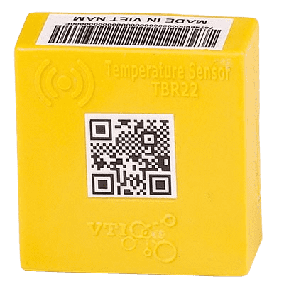
VTI-TS-26 outdoor clamp-on sensor on high-voltage conductor
Direct answer. The VTI-TS-26 is a long-range, battery-free, self-powered wireless contact temperature sensor engineered for extra-high-voltage (EHV) substations up to 500 kV, power transformer bushing palms, and overhead transmission lines. It harvests operating energy directly from conductor current from ≥ 1 A upward, transmits via LoRa sub-GHz up to 3 km line of sight, and measures across −40 to +125 °C with ±0.2 °C accuracy (−10 to +65 °C).
Type-tested to 500 kV at independent high-voltage laboratories with partial discharge of 8.7 pC (acceptance < 10 pC) and lightning impulse withstand of −1500 kV. Aligned directly with CIGRE Technical Brochure 999 Table 2.8-1 for transformer and circuit breaker thermal supervision.
Configurable for regional sub-bands (AS923, IN865, EU868) with Listen-Before-Talk (LBT) and <1% duty cycle. Spans large substation yards and gantry towers.
Type-tested to 500 kV with 8.7 pC partial discharge and −1500 kV lightning impulse withstand. Proven immunity against high-voltage switching surges.
Starts continuous measurement at 1 A (vs ~5 A for comparable products), preserving DLR trend data during light-load and solar peak suppression.
Current-transformer induction eliminates chemical battery cells. True lifetime operation matched to the service life of the primary asset.
Sealed potted construction designed for tropical monsoons, solar UV degradation, coastal salt fog, and industrial airborne pollutants.
Direct contact conductor temperature feeds dynamic ampacity algorithms, unlocking 10–30% extra transmission capacity on existing corridors.
| Parameter | Specification |
|---|---|
| Model Name | VTI-TS-26 (VTI-TS series, previously catalogued as TBR22 / TBR22-STE / TBR22-BTE) |
| Power Supply | Current-transformer induction energy harvesting, 100% battery-free |
| Minimum Start Current | ≥ 1 A primary alternating current on monitored conductor |
| Measuring Temperature Range | −40 °C to +125 °C |
| Measurement Accuracy | ±0.2 °C within −10 to +65 °C; ±0.5 °C across rest of range |
| Operating Ambient Temperature | −40 °C to +85 °C; humidity 0–100% (IP68) |
| Type-Tested System Voltage | Type-tested to 500 kV (EHV / UHV qualified) |
| Partial Discharge at 500 kV | 8.7 pC (acceptance criterion < 10 pC) |
| Lightning Impulse Withstand | −1500 kV standard full wave impulse |
| Wireless Protocol | LoRa sub-GHz (AS923, IN865, EU868 configurable per country) |
| Transmission Range | Up to 3 km line of sight in unobstructed substation switchyards |
| Radio Compliance | Duty cycle < 1%, Listen-Before-Talk (LBT), regional EIRP limits |
| Reporting Interval | Adaptive, 5 to 30 minutes (dynamic acceleration during thermal surges) |
| Mounting Method | Clamp-on with stainless-steel locking ties and high-field magnetic grip |
| Installation Safety Requirement | Installed strictly with the circuit isolated, earthed, and proved dead during planned outages |
| International Standards | CIGRE Technical Brochure 999 Table 2.8-1, IEEE Std 2969-2025, NFPA 70B |
| Host Gateway | VTI Gateway GW22-D dual-band (Modbus TCP, MQTT over TLS, IEC 60870-5-104) |
Per CIGRE TB 999 Table 2.8-1 and our 14 Critical Mounting Positions guide, VTI-TS-26 is deployed at:
Includes complete 500 kV HVLAB type-test reports, partial discharge certifications, dimensional drawings, and application engineering review.
Request VTI-TS-26 Test Reports