Substation Temperature Monitoring Case Study: Continuous Thermal Monitoring at 110 kV Hoi Hop and 22/0.4 kV Ao Hai (EVNNPC)
Field results from a wireless continuous thermal monitoring (CTM) pilot on the Vietnamese distribution grid, and how the findings map to IEEE Std 2969-2025, CIGRE Technical Brochure 999 and NFPA 70B (2026). By Nguyen Cao Ninh, Bui Viet Hung, Vu Cong Thuc, Nguyen Van Ba and Tran Anh Tung — VTI Corp, Hanoi. Published 30 September 2026.
Summary. From November 2023, VTI Corp installed wireless temperature sensors at two substations operated by Vinh Phuc Power Company, part of Northern Power Corporation (EVNNPC): the 110 kV Hoi Hop substation and the 22/0.4 kV Ao Hai substation. More than 20 temperature points were monitored continuously, alongside current, voltage and phase balance.
The system flagged two real defects. At Hoi Hop, it raised phase-deviation warnings on the 110 kV bushing terminals of the 63 MVA T2 transformer, appearing at peak load. At Ao Hai, it detected abnormal heating on phase C of a branch MCCB; the utility confirmed the defect on 21 November 2023 and repaired it on 27 November 2023, after which temperatures returned to normal. Readings agreed with handheld infrared checks to within 0.4–3.2 °C.
This is the practice described by IEEE Std 2969-2025 (CTM of switchgear up to 52 kV), listed as “energy harvesting thermal sensor” in CIGRE TB 999 Table 2.8-1, and permitted by NFPA 70B (2026) §7.2.1.2 and §7.4.5.
Key facts
- Utility
- Vinh Phuc Power Company — Northern Power Corporation (EVNNPC), Viet Nam
- Sites
- 110 kV Hoi Hop substation; 22/0.4 kV Ao Hai distribution substation
- Start of monitoring
- November 2023
- Measuring points
- More than 20 temperature points, plus current, voltage and phase-balance measurement
- Equipment monitored
- Current transformers, disconnectors, circuit breakers, transformer bushings (HV, MV, LV), transformer tank, main and branch MCCBs
- Validation
- 0.4–3.2 °C difference against a handheld thermal camera
- Defects found
- 2 — transformer bushing terminals (110 kV); branch MCCB phase C (0.4 kV), repaired
- Original publication
- Electrical Engineering Portal, 5 January 2026
Why substation joints need continuous monitoring
Most thermal failures in a substation start at a connection: a bolted busbar joint that has lost clamping force, a cable lug that was poorly crimped, a breaker contact that has worn. Contact resistance rises, local heating rises with I²R, and the process accelerates. CIGRE TB 999 (§2.2.1) describes the same chain — poor conductive contact, increased contact resistance, local overheating, corrosion and eventually flashover.
Periodic infrared thermography remains the most common check, but it has three structural limits:
- It is a snapshot. A joint that only overheats at evening peak can look normal during a daytime survey.
- It needs line of sight. Terminations behind covers, boots or closed compartment doors cannot be seen.
- It is infrequent. Surveys are typically annual or semi-annual; a defect can develop between two visits.
The CIGRE survey reported in TB 999 (p. 197) found that 94.34 % of responding utilities still rely on manual inspection and 75.47 % on infrared thermography at HV–MV substations. Continuous monitoring closes the gap between those visits.
What was installed
110 kV Hoi Hop substation
Wireless contact temperature sensors were fitted at 11 locations on the 110 kV equipment — current transformers, disconnectors and circuit breakers. On the T2 power transformer (115/38.5/23 kV, 63 MVA), sensors were fitted to the HV, MV and LV bushing terminals and to the main tank, and a fixed thermal camera was added for area coverage of the transformer.
22/0.4 kV Ao Hai substation
At the distribution substation, sensors were fitted to the transformer bushings, the main MCCB and the branch MCCBs of the 0.4 kV board. Phase current transformers were added so that load current, voltage and phase balance could be read alongside temperature.
What was monitored and how warnings were set
The system recorded more than 20 temperature points — bushing contacts, breaker and disconnector terminals, transformer oil and ambient temperature — and displayed them on a web interface and a mobile application. Four warning types were configured:
- Overheating, either against an absolute limit or as a temperature difference between phases of the same circuit;
- Overload, from the measured load current;
- Voltage outside limits;
- Phase unbalance.
The phase-to-phase comparison is the most sensitive of these: three phases of one circuit share the same load and ambient, so a joint that runs hotter than its neighbours is the clearest early sign of a contact defect.
How accurate is it compared with infrared?
Sensor readings were checked against a handheld thermal camera. The differences ranged from 0.4 °C to 3.2 °C, which the authors attribute to the combined tolerance of the sensors and of the handheld instrument. For context, handheld thermal cameras are commonly specified at ±2 °C or ±2 % of reading, and their readings depend on emissivity settings and viewing angle.
IEEE Std 2969-2025 (Annex A.2) makes the relevant point: “the accuracy of the measurement is potentially less important than detecting temperature changes over time.” A continuous record that shows one phase drifting away from the other two is more useful for maintenance than a single precise reading.
Defects detected
Case 1 — 110 kV bushing terminals, T2 transformer, Hoi Hop
Temperatures on the phase A and phase C 110 kV bushing terminals of T2 rose during peak-load hours, and the system raised phase-deviation warnings. Thermal images of the terminals confirmed the heating pattern. Because the rise appeared mainly at peak load, it is the type of defect an off-peak infrared survey tends to miss.
Case 2 — branch MCCB phase C, Ao Hai
The monitoring data showed an abnormal temperature rise on phase C of branch MCCB 2 in the 0.4 kV board. Technicians inspected on 21 November 2023 and confirmed the overheating. On 27 November 2023 the circuit was taken out of service, the contact surfaces were reworked and the cable terminal was re-crimped. After energisation, temperatures returned to normal — a defect found, scheduled and corrected within one week through a planned outage.
Lessons learned — and what has changed since
The pilot also showed the limits of the 2023 configuration. We publish them because engineers evaluating CTM will ask:
| Observed in the pilot | Current approach |
|---|---|
| Installing or replacing a sensor required the circuit to be de-energised. | Unchanged, and deliberate: sensors are installed with the circuit isolated, earthed and proved dead, inside the operator's planned outage window. Once fitted, no further outage is needed — the sensor has no battery to replace. |
| Limited space for the phase current transformers used to measure load current in crowded 400 V cabinets. | Separate CTs are needed only where load current, voltage and balance are to be measured. The temperature sensors themselves need no auxiliary supply: the VTI-TS sensor powers itself from the conductor it measures, from 1 A of primary current. |
| Backhaul over a 3G/4G SIM or station Wi-Fi occasionally dropped. | The GW22 gateway has a wired RJ45 Ethernet output (Modbus TCP or MQTT) to the station network, and the VTI platform can run on premises. |
How this case maps to IEEE 2969, CIGRE TB 999 and NFPA 70B
The two sites span three voltage levels, so different references apply to different parts of the installation. None of them is a certification scheme; the table shows where each reference speaks to what was done.
| Reference | Scope | What it says | Where it applies in this case |
|---|---|---|---|
| IEEE Std 2969-2025 Guide for CTM of switchgear and MCCs up to 52 kV | ≤ 52 kV | §1.2: CTM can complement or replace periodic infrared surveys. §5.3.1(d): lightly loaded joints need close supervision. §5.5.1/§5.6.1: sensors must not reduce insulation level. Annex A.2: trend matters more than absolute accuracy. | Ao Hai 22 kV and 0.4 kV equipment, including the MCCB defect (Case 2). |
| CIGRE TB 999 (JWG B3.D2.62, 2026) Lifelong supervision and management of substations | All voltages | Table 2.8-1: for transformer and circuit-breaker thermal needs, at HV–MV and MV–LV, lists “energy harvesting thermal sensor”. §1.2.4: wired sensors dominate today, but utilities' plans lean toward wireless, especially for temperature. | Hoi Hop 110 kV equipment and the T2 bushing terminals (Case 1) — above the 52 kV scope of IEEE 2969. |
| NFPA 70B, 2026 edition Standard for electrical equipment maintenance | Electrical equipment maintenance programmes | §7.2.1.2: permanently mounted thermal sensors are permitted to monitor connections and terminations. §7.4.5: continuously monitoring, permanently installed devices are permitted to satisfy §7.4.1–7.4.4. §9.1.1.1: continuous monitoring may be used when setting maintenance intervals. | The 0.4 kV board at Ao Hai; most relevant to industrial and commercial owners that run an NFPA 70B maintenance programme. |
| QCVN 26:2025/BCT Vietnamese national technical regulation, power grid | AC grid and substations ≤ 500 kV | Clause 1.9.5.3 (2): periodic checks of the heating temperature of busbar joints carrying 1000 A or more, using dedicated instruments. Annex M sets maximum temperatures for contacts and joints. | Both sites, as the legally binding reference in Viet Nam. The regulation does not mandate online monitoring; CTM is a way to carry out the inspection duty continuously. |
One caution for NFPA 70B users. Under §9.2.1.1–9.2.1.3, unaddressed notifications from a continuous monitoring system can move equipment from Condition 1 (60-month intervals for switchgear in Table 9.3.2) to Condition 3 (12 months). A CTM system that produces nuisance alarms therefore raises maintenance cost rather than lowering it. Alarm logic based on phase-to-phase comparison, as used here, is the practical defence.
The VTI-TS solution today
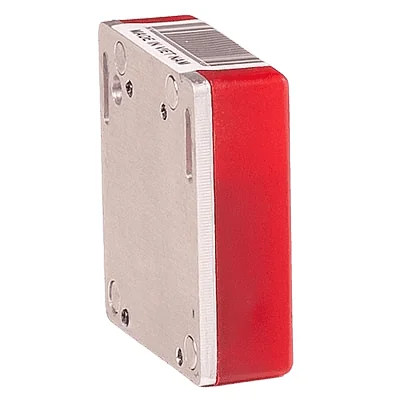
The current VTI continuous thermal monitoring system is built on the VTI-TS sensor family (previously catalogued as TBR22) and the GW22 gateway.
| Parameter | VTI-TS-22 | VTI-TS-26 |
|---|---|---|
| Typical use | Enclosed switchgear, MCCs, LV boards | Outdoor yards, bushings, disconnectors, dispersed points |
| Power | Self-powered from the measured conductor, battery-free, from 1 A primary current. Battery version available for points without load current. | |
| Type test | Up to 500 kV: partial discharge 8.7 pC (acceptance < 10 pC), lightning impulse −1500 kV (HVLAB, VILAS 491) | |
| Measuring range | −40 to +125 °C | |
| Radio | Bluetooth Low Energy 2.4 GHz, about 100 m | LoRa AS923, up to 3 km line of sight |
| Reporting | Adaptive, every 5 to 30 minutes | |
| Gateway | GW22 / GW22-D (dual-band): up to 1,000 sensors, receive-only, Ethernet output via Modbus TCP or MQTT | |
What we do not claim
- IEEE Std 2969-2025 is a guide and has no certification programme. We map our system against its clauses; we do not claim “IEEE 2969 compliance”.
- NFPA 70B is not a legal requirement in Viet Nam. It is relevant to owners who choose to run an NFPA 70B maintenance programme, such as many data centres and FDI factories.
- Self-powering needs alternating current. DC busbars, battery strings and PV strings require the battery version.
- The system supports condition-based maintenance. It is not a fire-detection system.
- Native IEC 61850 is on the development roadmap, not a current capability.
Frequently asked questions
What is continuous thermal monitoring (CTM) in a substation?
CTM uses permanently installed sensors to measure the temperature of electrical connections — busbar joints, cable terminations, breaker and disconnector contacts, bushing terminals — around the clock, instead of relying on periodic infrared surveys. IEEE Std 2969-2025 is the guide for CTM of switchgear and MCCs up to 52 kV.
Which sensor type does CIGRE TB 999 list for transformer and breaker thermal monitoring?
Table 2.8-1 of CIGRE Technical Brochure 999 lists the “energy harvesting thermal sensor” for transformer thermal and circuit-breaker thermal needs at both HV–MV and MV–LV levels. The VTI-TS family is a sensor of this type.
Can continuous monitoring replace infrared inspection under NFPA 70B?
NFPA 70B (2026) §7.4.5 permits continuously monitoring, permanently installed temperature measurement devices to satisfy the thermography requirements of §7.4.1–7.4.4. It permits this; it does not require it, and the sensors must cover the points the inspection programme is meant to cover.
How close are wireless sensor readings to a thermal camera?
In this EVNNPC pilot the difference against a handheld thermal camera was 0.4–3.2 °C. For maintenance decisions, the trend and the phase-to-phase difference are more informative than the absolute value, as IEEE Std 2969-2025 Annex A.2 notes.
Does installing the sensors require an outage?
Yes. VTI sensors are installed with the circuit isolated, earthed and proved dead, within the operator's planned outage. After that, no further outage is needed for the sensor, because it has no battery to replace.
What is the minimum current for a self-powered VTI sensor?
The VTI-TS sensors operate continuously from a primary current of 1 A. Points with no load current use the battery version.
Planning a CTM pilot? VTI supplies and commissions a pilot of 20–40 measuring points with one GW22-D gateway, integrated with your SCADA or BMS. Contact [email protected] or read the clause-by-clause standards mapping.
Source and citation. This page is VTI Corp's own account of a field study first published as “A Case Study of Substation Temperature Monitoring System” in Electrical Engineering Portal on 5 January 2026, updated with the current product specification and the standards mapping above.
References. [1] IEEE Std 2969-2025, IEEE Guide for Continuous Thermal Monitoring of Switchgear and Motor Control Centers up to 52 kV. [2] CIGRE Technical Brochure 999, Lifelong Supervision and Management of Substations by Use of Sensors, Mobile Devices, Information and Communication Technologies, JWG B3.D2.62, August 2026. [3] NFPA 70B, Standard for Electrical Equipment Maintenance, 2026 edition. [4] QCVN 26:2025/BCT, National technical regulation on electrical engineering — power grid, in force 1 June 2026.
Related: Substation temperature monitoring · Busbar hot-spot monitoring · Continuous thermal monitoring and NFPA 70B